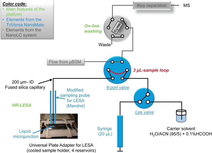
Figure 1.
Schematic representation of flow connections between the elements of the μLC system (in gray) and the automated sampler device (blue). Main features of the analytical platform are indicated in green. The route of the sample loop is shown in red. The 6-port valve is in the “sample loading” position. HR: high spatial resolution. LESA: liquid extraction surface analysis. BSM: binary solvent manager.

