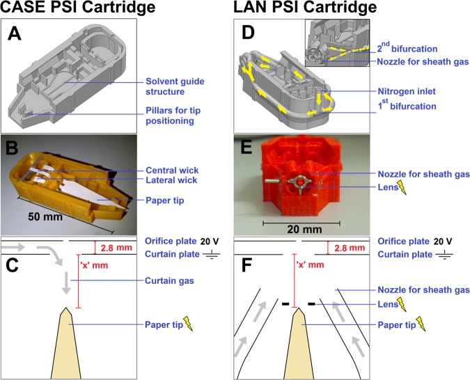
Figure 1.
(A–C) PSI cartridge configuration for controlled and symmetric elution (CASE). (D–F) PSI cartridge with electrostatic lens and nozzles for sheath gas delivery (LAN). The figure shows (A, D) the Solidworks design, (B, E) a 3D-printed device (without the lid), and (C, F) schematic top views of the experimental configurations for PSI. Yellow arrows in D show the distribution of air through the network of ducts, bifurcations and nozzles; the inset in D shows a cross-sectional front view along the length of the gas tubes.

