Fig. 1.

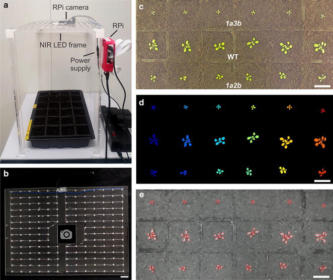
Setup of the image capture system. a The image capture system (ICS) consisted of a NIR LED frame, a Raspberry Pi (RPi) computer and a RPi camera (PI NoIR). b The NIR LED frame consisted of 173 NIR LEDS arranged in parallel circuits. The design allowed the camera to be positioned centrally in the frame (see Additional file 1 for assembly guidelines). c Arabidopsis WT plants and Rubisco mutants 1a3b and 1a2b (18 DAG) under visible light (VIS) conditions captured by the ICS with the NIR LEDs off. d Automated segmentation of the plants shown in (c). e Near-infrared (NIR) image of plants shown in (c) taken in the dark illuminated by NIR LEDs. The last image of the 18th light period (c) was used as a starting mask for the following dark period image (e). The outline of the active contour mask is shown in red. Bars: B = 40 mm; C, D, E = 25 mm
