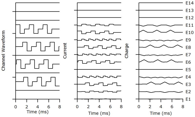
Figure 2.
The stimulus used was designed to represent a ‘worst case’ scenario in terms of charge recovery time and degree of focusing using FMP stimulation. The left panel represents the stimulus waveforms to be delivered to specified channels and is comprised of 4 biphasic pulse trains on non-adjacent FMP channels. Note that these waveforms represent the positions of focused channels that will be delivered to the neural elements, not the current delivered to each electrode. The middle panel represents the currents to be delivered to specified electrodes. The currents are calculated based on the sum of all the channel waveforms (left panel) transformed into appropriate electrode currents as described in the text. They are designed to achieve maximal focusing of each channel. The right panel represents the net charge delivered to each electrode. Unlike the very rapid charge recovery associated with a conventional biphasic current pulse delivered sequentially, complete charge recovery using FMP stimulation was not ensured until the end of the 8 ms stimulus frame when all electrodes were shorted for 100 μs. The 8 ms stimulus was then repeated in a continuous loop.

