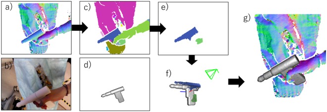
Fig. 3.

Overview of the 3D tool tracking process
a Depth image with surface normals in input frame
b Colour image in input frame
c Geometrical segmentation result
d Visible part of 3D tool model in the previous frame
e Detected TS in input frame
f ICP between the 3D tool model and TS
g Registered 3D tool model in depth image
