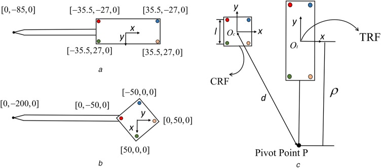
Fig. 2.
Two surgical tool configurations
a Fiducials' configuration and tool-tip position of the first surgical tool
b Fiducials' configuration and tool-tip position of the second surgical tool. Notice that the two fiducial configurations are planar which means these fiducials lie on one plane
c CRF and TRF are indicated by the x and y axes, l is the side length of CRF rigid body, d is the distance between CRF origin and the pivot point P, is the distance from TRF origin to the tip position P. z axis is perpendicular to both x and y axes. CRF-attached and TRF-attached fiducials are denoted as coloured solid circles

