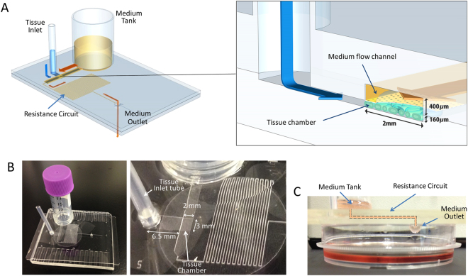
Figure 1.
The pumpless microfluidic device. (A) Schematic 3-D image of the PL microfluidic device, showing medium tank, tissue inlet, resistance circuit, and medium outlet. On the right, an enlarged view of the portion encompassing the tissue chamber, medium flow channel, and tissue inlet route is shown. (B) Photographs of the device. In the right, closer view of tissue chamber and resistance circuit is shown. (C) Low-lateral view of the device demonstrating the medium flow route, finally dropping down to the collecting dish.

