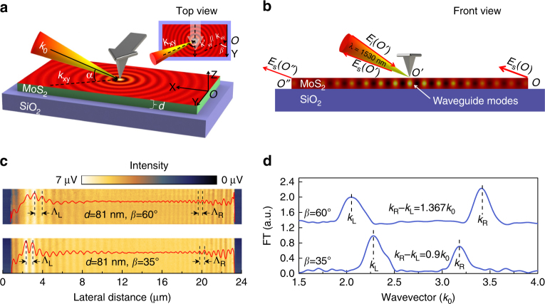
Fig. 1.
Schematics of the experimental setup and the near-field imaging principle. a Three-dimensional schematic of the near-field setup. The sharp edges of MoS2 nanoflakes are aligned to the Y axis and the s-SNOM tip scans along the X axis. Inset is the top view of the experimental setup. α is the angle between the illumination wavevector k 0 and its projection in the X–Y plane k xy, β is the angle between k xy and the investigated sample edges. b Front view of the experimental setup. The tip-launched waveguide modes are scattered into free space at the sample edges and interfere with the tip-scattered light at the photodetector. c Near-field images and real-space fringe profiles of the 81-nm-thick MoS2 sample with β = 60°and β = 35°, respectively. ΛL is the fringe spacing at the left half of the near-field images while ΛR is that at the right half. d Momentum–space spectra of the fringe profiles in c, the difference between the left and right side apparent wavevectors decreases with the reduction of β

