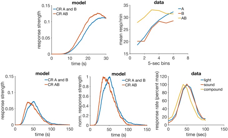
Fig 10. Disinhibition of delay and compound peak procedure.
Top row: simulation (left) and data (right) of disinhibition of delay. Bottom row: simulation (left and middle) and data (right) of a compound peak procedure. The middle panel is a normalized (proportion of maximum response strength) version of the left panel. Data plot redrawn from Figure 13 in [44]. Model parameters: m = 0.25, θ = 1, σ = 0.18, αt = 0.75, αV = 0.1, H = 5.

