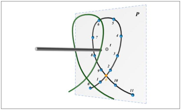
Figure 13.
Loop projection and detection. Each line segment forming the thread (curve in green) is first projected onto P. A thread loop is determined by checking whether there are two line segments (1–2 and 9–10) intersecting with each other at e (point in orange), and form a closed loop loopP: e-2-3-4-5-6-7-8-9-e. The thread is looping around the tool when the projection of the tool (i.e., t) is inside the loopP.

