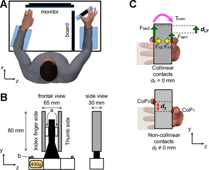
Fig. 1.

Experimental setup. A: top view of the experimental setup. The subject is shown contacting the handle with the right thumb and index fingertip while the left hand is kept flat on the table. When the subject relaxed between trials, both hands were kept flat and relaxed. Note that the board was placed so as to prevent subjects from seeing their right forearm and hand. Foam cushions were placed underneath the forearms and wrist for subjects’ comfort. B: front and side views of the grip device; a and b denote force/torque sensors and active markers for motion tracking, respectively. A mass (400 g) was added to the slot at the bottom of the device on the index finger side. C: front views of the object showing the thumb and index fingertip center of pressure (CoP; red circles) of the hand located at the same (collinear contacts; top) or different y-coordinates (non-collinear contacts; bottom). The vertical distance between thumb and index fingertip CoP is denoted by dy. Top panel also shows normal and tangential forces generated by each digit (Fn and Ftan) and the torque generated by the digits (Tcom) to compensate the torque caused by the object’s asymmetrical mass distribution (mass added to the index finger side of the object).
