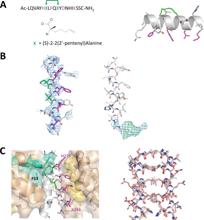
FIG 3.
spIKKγ and the crystal structure of the GB1–ks-vFLIP–spIKKγ complex. (A) (Left) Sequence of the in silico-designed IKKγ-mimetic peptide (spIKKγ), together with the position and structure of (S)-2-(2′ pentenyl)alanine used to replace Q236 and E240 (green). The key cleft 1 binding residues are depicted in magenta. (Right) Energy-minimized model of spIKKγ highlighting the aliphatic linker (green) after cyclization and its position relative to the cleft 1 binding residues on the opposite face of the helix. (B) (Left) Refined coordinates of spIKKγ superimposed on the initial 2mFo-DFc electron density map (blue, contoured at 1σ), calculated using the coordinates of ks-vFLIP from PDB entry 3CL3 alone after molecular replacement. (Right) 2mFo-DFc (blue, contoured at 1σ) and mFo-DFc (green, contoured at 3σ) electron densities associated with the C-terminal cysteine of one spIKKγ peptide. (C) (Left) ks-vFLIP–spIKKγ dimer interface (for clarity, one IKKγ monomer is depicted as a cartoon [light gray]). The cleft 1 interactions (magenta for spIKKγ and yellow-orange for cleft 1 in ks-vFLIP) are entirely conserved. The aliphatic staple (green), though partially ordered, projects into the cavity between cleft 1 and cleft 2 (cyan) of the opposite ks-vFLIP monomer alongside F53. (Right) spIKKγ-spIKKγ dimer (gray) superimposed on the analogous interface in the ks-vFLIP-IKKγ(150–272) complex (pink) shows an almost identical configuration and arrangement of residues.

