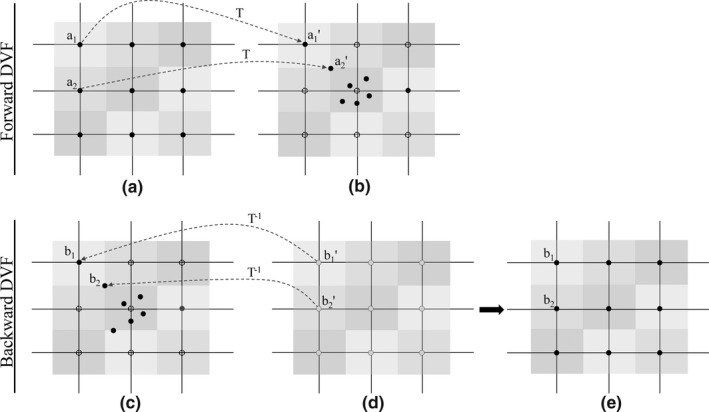
Figure 2.

Illustration of the forward DVF and backward DVF. (a) Representation of the grid nodes (solid points) superimposed on the pCT, and the node was located on the center of each voxel, the different color was used to differentiate the different voxel. (b) Representation of the CBCT. Driven by the forward DVF, a perfect match of a1 and a1′ was accomplished, while a2 was not transformed to the corresponding node, but someplace nearby, e.g., a2′. The dotted nodes represented that no points were transformed to here. (c) pCT and (d) CBCT, driven by the backward DVF, nodes superimposed on the CBCT were transformed to the voxels of pCT. (e) mCBCT with HU value of pCT.
