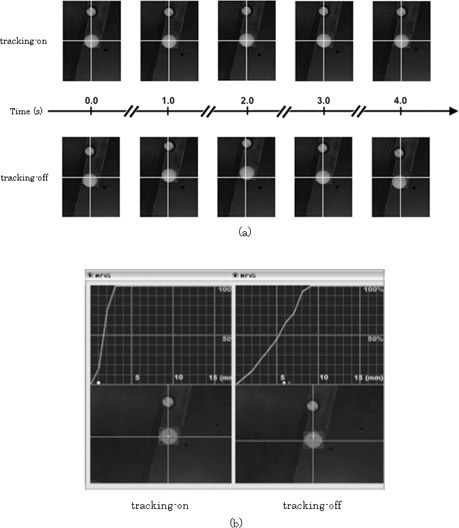
Figure 6.

Beam's eye view images from CCD camera (a): top panel images correspond to the “tracking‐on” setting, and those in the bottom panel were obtained with the “tracking‐off” setting. In the top panel, the ball was placed approximately at the center of the BEV images, whereas in the bottom panel images it was placed far from the center of the BEV images due to its motion. Screen of VideoCapture (b): “tracking‐on” setting (left) and “tracking‐off” setting (right). The top panels show the tracking error probability histograms.
