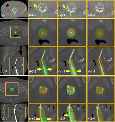
Figure 10.

Segmentation of inhomogeneous targets (CT). The ROIs, which are indicated by the yellow boxes, are shown in the zoomed‐in views for clarity. (a) The vertebra in CT image (case 4): (a) SPs labeled inside (green) and outside (red) of the vertebra; (a) segmentation (red curves) by RW; (a) segmentation (red curves) by GC; (a) segmentation (red curves) by SPARSE. The green curves in (a) represent the ground truth segmentation, and the yellow arrow in (a) indicates undersegmentation in RW; (b) and (c), the T&C applicator and the T&O applicator in CT image respectively (case 5, 6): (b‐c) SPs labeled inside (green) and outside (red) of the applicator on only one transversal slice; (b‐c) segmentation (red masks) by RW; (b‐c) segmentation (red masks) by GC. (b‐c) segmentation (red masks) by SPARSE. Rows in (b) and (c) are transversal and sagittal slices, respectively. The green masks in (b) and (c) represent the ground truth segmentation. The yellow arrows in (b‐c) indicate the undersegmentation in RW and GC, respectively.
