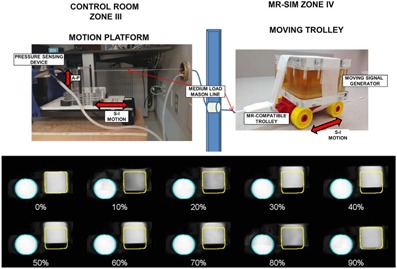
Figure 4.

(Top) Experimental setup for 4D MRI phantom study, including the motion platform and components located in the control room that translate the MR‐compatible trolley located in the MR‐SIM bore. (Bottom) Coronal view for a ten‐phase, amplitude‐based triggered 4D MRI for a signal generator phantom translating in the superior–inferior direction (square object, sinusoidal breathing pattern, 3 s period). The percentages describe the breathing phases, with 0% representing end‐inhale and 50% representing end‐exhale. The round static signal generator is also shown in the field of view.
