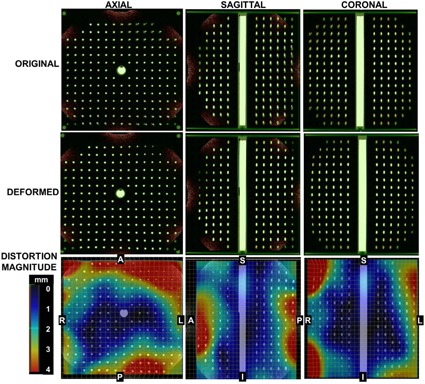
Figure 6.

(Top row) Blended overlay of the original CT‐SIM (green) and MR‐SIM data (orange) prior to deformable image registration. Mismatches in marker location can be observed between datasets, particularly near the edges of the field of view. (Middle row) Overlay of CT‐SIM and MR‐SIM data after deformable image registration, showing the resolution of image distortions. (Bottom row) Vector distortion magnitude between the CT‐SIM and MR‐SIM datasets demonstrate the distortions occurring near the edges of the field of view. For reference, centroid‐to‐centroid marker spacing is 2.5 cm in‐plane and 2.7 cm along the z‐axis, and the registration field of view was in the right–left, anterior–posterior, and superior–inferior, respectively.
