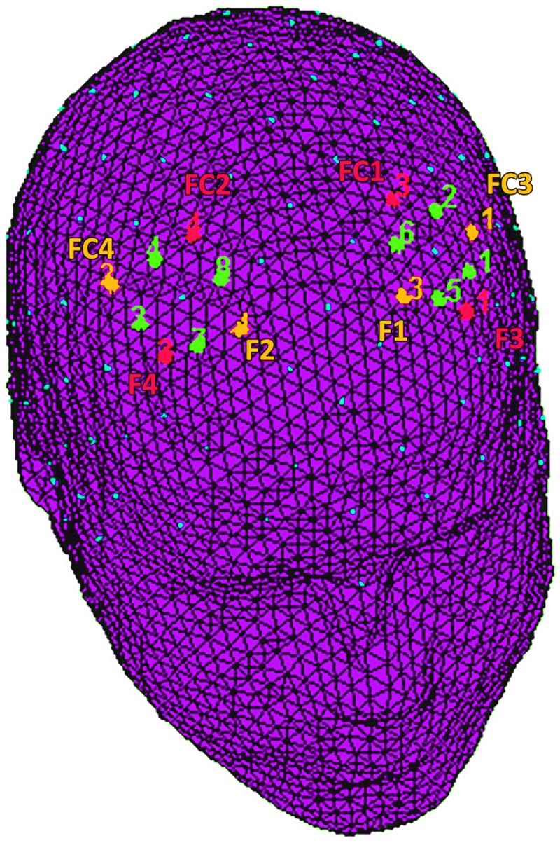
Fig 2. fNIRS montage.

The location of NIRS channels. The emitters (orange) were placed on positions FC3-FC4 and F1-F2, while detectors (red) were placed on FC1-FC2 and F3-F4. The resulting channels (green) were as follows: Ch 1 and Ch 3 correspond to the left and right DLPFC. Ch 2 and Ch 4 correspond to the left and right DPMC. Ch 5 and Ch 7 correspond to the left and right FEF. Ch 6 and Ch 8 correspond to the left and right SFG.
