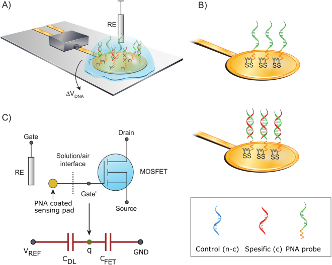
Figure 1.
(A) Schematic of the DNA sensor using PNA probe (green) monolayer on gold. The gold pad is the extended-gate and it is coupled to the gate of a discrete MOSFET. (B) Illustrates the probe configuration with and without the hybridized complementary target. In the box the used PNA and DNA strands are shown (i) control (denoted as n-c, blue), (ii) specific target (denoted as c, red), (iii) PNA probe (green) and its linker (orange). (C) Equivalent circuit and a simplified capacitive model of the sensor.

