Figure 1.
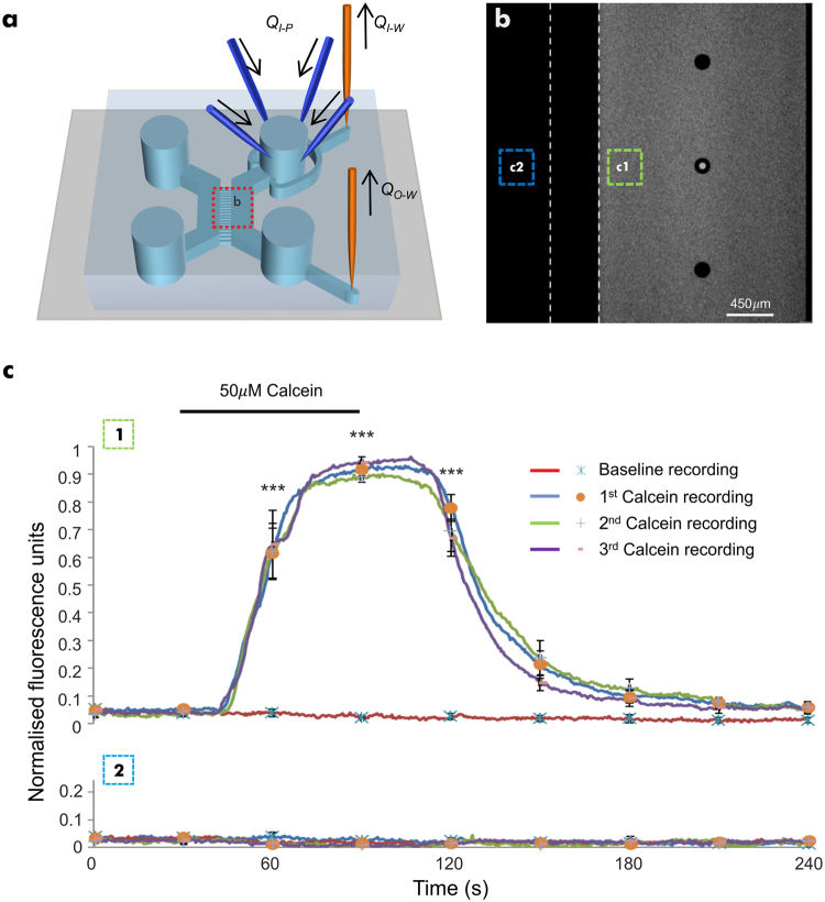
Development and characterisation of the microfluidic perfusion system. (a) Schematic representation of a dual chamber microfluidic device with inlet/outlet needle ports for the direct perfusion/withdrawal of fluid in/from the wells. Computer-controlled syringe pumps were used for fluid injection and withdrawal. (b) A representative image showing absence of cross contamination in the naïve chamber and microchannels during perfusion of calcein (50 µM) in the perfused chamber (dashed lines indicate the microchannel array separating the perfused chamber from the naïve chamber). (c) Fluorescent profiles in the perfused (c1) and naïve (c2) chambers, respectively upon repeated delivery of calcein solution from 3 different pumps. This demonstrated a lack of cross-contamination between the chambers and the robustness of the perfusion protocol (n = 9 devices). Data is expressed as mean ± S.E.M. (one-way ANOVA with post-hoc Tukey’s test. ***Denotes P < 0.001, relative to baseline readings).

