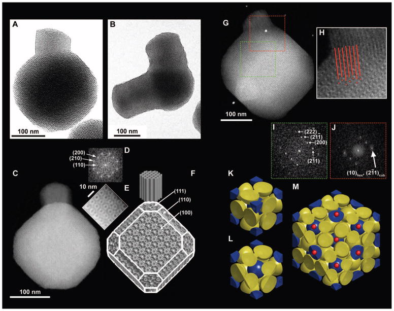
Fig. 1. Geometrical description of mc-MSNs.
(A) BF-TEM image of a branch with hexagonal pore structure emanating from one corner of a core with cubic pore structure. (B) BF-TEM image showing two branches emanating from two corners of the core. (C) HAADF-STEM image of (100) projection of the core. (D) FFT of the entire cubic core part of the image in (C). (E) Magnified image of the top right edge of the particle in (C). (F) Schematics of a model mc-MSN. Miller indices for some of the representative facets are provided as a visual guide. (G) HAADF-STEM image of a mc-MSN exhibiting the (110) projection of the core. (H) Magnified image of the connecting region between the core and branch in (G), with red lines and dots indicating projected vacancy positions to demonstrate the structural registry/epitaxy. (I) FFT of the cubic core region in (G) (green box). (J) FFT of the connected region in (G) (red box). (K to M) Model visualization of the epitasial relationship of mesopores at the interface of (111) Pm3̄n cubic and (0001) P6mm hexagonal planes. (K) Unit cell of the Pm3̄n cage-like structure exhibiting body-centered cubic lattice micelles (blue spheres) and pairs of micelles on the faces (yellow spheres). (L) (111) plane cut of a single unit cell. (M) (111) plane cut of a 2 × 2 × 2 lattice, additionally showing the positions of expected hexagonal channels as small red dots.

