
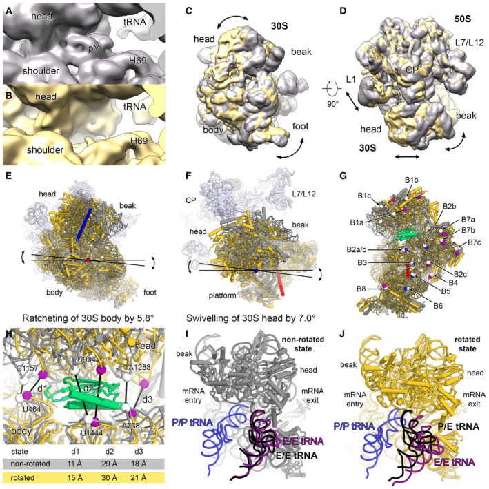
Figure EV5. Plastid translation factor pY .
-
A–DThe 70S map with density for pY in the mRNA channel is shown in grey (A) and the empty 70S map is shown in yellow (B). The 70 maps were overlaid using only the density of the 50S. Comparison of the overlaid maps, shown in 30S subunit view (C) and top view (D). The rotation of the 30S subunit is indicated with arrows.
-
E, FThe body and the head domains of the 30S model were independently fitted into the cryo‐EM map of the rotated state. The rotation angle of the 30S body rotation (ratcheting) (E) and the 30S head rotation (swivelling) (F) were measured using PyMOL, and the rotation axes are shown in red and blue, respectively.
-
GIntersubunit bridges are affected by the 30S rotation. A selected residue of each intersubunit bridge is represented as white sphere in the non‐rotated state. The same residues are coloured in the rotated state either in blue, if the contact with the large subunit is maintained, or in purple, if the contact is lost. The intersubunit bridges and the differences between the rotated and the non‐rotated state are described in Appendix Table S4.
-
HDistances (d1, d2 and d3) between backbone phosphates of selected rRNA residues (spheres) in the non‐rotated (white) and the rotated state (purple) indicating a slight opening of the mRNA channel.
-
I, JtRNAs in the P/P‐ and E/E‐state from a crystal structure of the bacterial 70S ribosome in complex with mRNA and tRNAs (PDB 4V51; Selmer et al, 2006) are overlaid and shown in blue and purple, respectively. A tRNA (black) was fitted as rigid body into the 70S maps of the non‐rotated (I) and of the rotated state (J).