
Fig. 4.
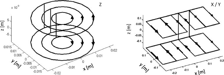
Simulation results of discrete current paths of X, Y and Z gradient. The Y gradient is not shown, as X is identical to Y (rotated 90° around the Z-axis). The connecting lines between gradient plates (top and bottom) are the back and return lines of the individual coil packs and thus do not provide any field input. Current directions are marked with arrows, and the gap was set to 230 mm