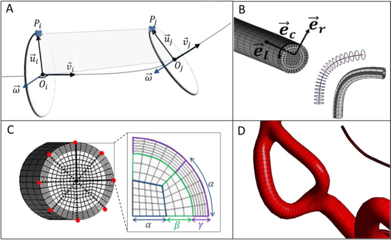
Figure 2.

Mesh generation for arterial segments between bifurcation to a terminal point (Bif-Term) and vessels connecting two bifurcations (Bif-Bif). (A) To build the mesh for a Bif-Term segment, a moving frame was implemented to sweep the local coordinate base vectors along the centerline. Reference point section, Pi, in the first cross-section was associated with the point, Pj, in the second cross-section using iso-planar mapping. (B) Longitudinal, circumferential and radial directions were used to adjust the resolution of the parametric meshes. Longitudinal subdivision can be chosen to refine the surface as a function of local diameter and centerline curvature. (C) For generating the volumetric meshes, cross-sections are swept and rotated along the longitudinal coordinate systems. Suitable selection of surface reference points (marked red) connect two bifurcation cross-sections to minimize rotation. The butterfly pattern allows for desired cross-sectional mesh refinement with the help of control parameters (α, β, and γ). (D) Subject-specific parametric mesh showing a section with two Bif-Bif segments forming a loop in the entrance of the anterior cerebral artery territory of subject II.
