
Figure 3.
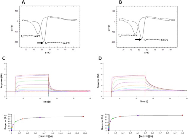
Interaction between Ref‐Cys367Ser and hYAP51–99/hTAZ14–56. A, B. Representative thermograms obtained in the FTDA with Ref‐Cys367Ser (1–2 µM) in the absence or presence of hYAP51–99 (A) or hTAZ14–56 (B) (20 µM). The melting temperatures (T m) were obtained by plotting the first derivative of the fluorescence emission (F) as a function of the temperature (–dF/dT). The curve minimum corresponds to T m. The arrow shows the thermal shift (ΔT m) observed upon peptide binding. The indicated T m have been measured for the experiments depicted on the figure. These T m are slightly different from the T m presented on Table II because these later are the average values obtained from several independent measurements. Upper panels: Representative sensorgrams obtained with Ref‐Cys367Ser immobilized on the chips and different concentrations of hYAP51–99 (C) hTAZ14–56 (D). Lower panels: Req vs [YAP60–100/TAZ17–56] plots. Req are the responses measured at equilibrium (plateau values in the above sensorgrams). These curves were fitted with 1 site binding equation model to determine K d.