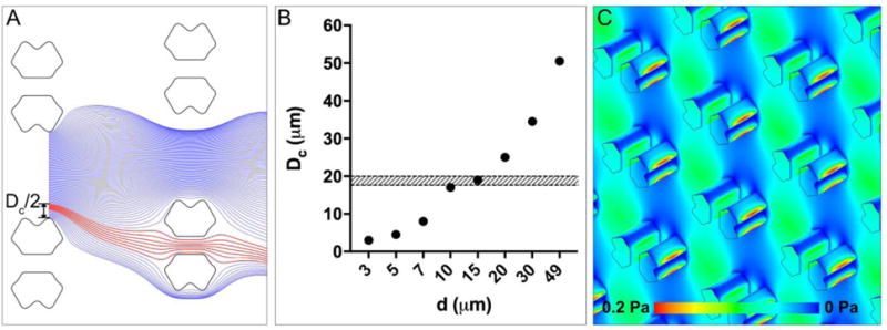
Figure 3.

The streamline orientation, basic principle, and shear stress of the trapping-DLD hybrid. (A) Top view diagram of streamlines in flow between two trapping obstacles (d=10 μm), demonstrating that any particles having a radius larger than /2 must be deflected by the trapping obstacle once it contacts the obstacle edge. The blue streamlines pass by the trap whereas the red ones go through it. (B) The critical diameter corresponding to the trapping obstacle located in the center of the array increases as the row-to-row shift (d) increases. The shaded-belt represents the size range of the microspheres used in this study (i.e., 17.6–20 μm). (C) The shear stress distribution within the array of d=10 μm, demonstrating a minimal shear stress of ≤0.2 Pa.
