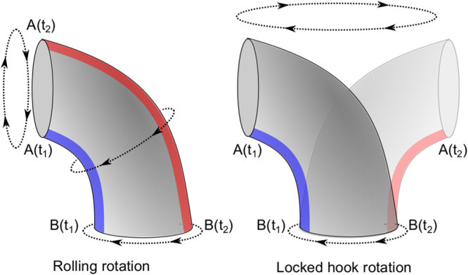
Figure 4.

Schematic representation of two possible rotation modes of the hook. The left figure shows the traditional rolling rotation, as a universal joint to transfer the rotation of the motor (which would be at the bottom on the schematic) to the filament (on the left). In this mode, the distance between each protein that composes the hook is modulated periodically to enable a rotation around a stable structure (here a bend to the left)3,4. The right figure shows the “locked-hook” rotation, where the entire hook rotates around the axis of the driving motor as a rigid structure. In both figures, the proteins along the blue strip must distribute along the red strip after half a turn.
