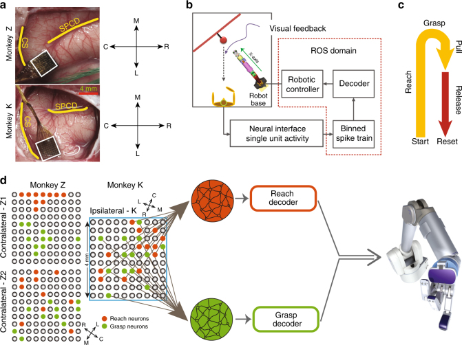
Fig. 6.
Schematic of the brain–machine interface and the motor task. a Cortical landmarks and the location of array implantation (SPCD, superior precentral dimple; CS, central sulcus). b Neural spike trains were decoded to generate control signals for the robot. Blocks within the dotted region were implemented in the Robotic Operating System (ROS) platform. c The behavioral task comprises reaching toward an object, grasping and pulling it through a partial trajectory back, and release d two neural subpopulations, reach (red) and grasp (green) were decoded independently to generate control velocities for the robot. Spatial distribution of the clusters are shown for the contralateral and ipsilateral experiments

