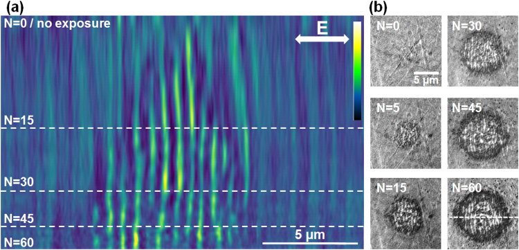
Figure 3.
Evolution on LIPSS formation on Zr-BMG in the moderate fluence regime (peak fluence of 0.15 J/cm2). (a) Evolution of a section profile with the number of pulses N (false colors). Sectional cuts made on LIPSS images are concatenated together for each N. The LIPSS pattern is detectable earlier in the pulse sequence. Topography features appear already from the first pulses and novel features develop laterally. Light colors represent zones of higher elevation. (b) Samples of the original SIM images. The direction of the electric field and the position of the sectioning line are given on the figures.

