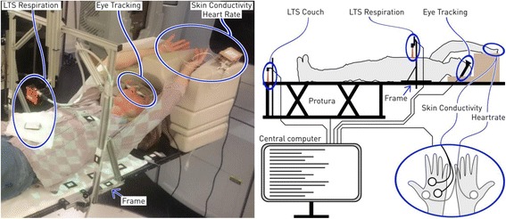
Fig. 1.

The volunteers were positioned supine with arms up. The left panel shows a volunteer with the sensors attached (blue ellipses). The right panel shows the schematic connection and placement of the sensors. The ellipse with two hands shows the placement of the electrodes for heartrate and skin conductivity measurements. LTS: laser triangulation system
