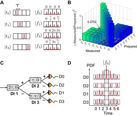
Fig. 2. Time-bin and phase states for d = 4 and the phase-state measurement scheme.

(A) Temporal (left) and phase (right) states for d = 4, with the phases determined from Eq. 1. (B) Probability of detection when each input state is measured in both bases. (C) Measuring the phase states with a cascaded interferometric tree, where the relative time delay of the first unequal-path delay-line interferometer (DI 1) is twice the delay of DI 2 and DI 3. The phase of DI 3 is set to π/2. (D) Expected photon probability distribution at the output of the interferometers when the phase state |f0〉 is injected into the system.
