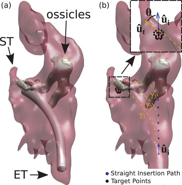
Fig. 3.

Simulated endoscopy of the Middle Ear. Figure (a) shows an example of endoscope insertion: the device shown here has a diameter of 1.40 mm and has been bent in such a way to point towards the sinus tympani (ST). Figure (b) illustrates how insertion paths γi are generated. The endoscope enters the ME following a straight path which coincides with the orientation of the Eustachian Tube (measured in the CT scan). After an initial straight motion of arbitrary length, the endoscope is bent along a constant curvature arc towards a target point. Target points are generated using a spherical grid in the proximity of the target anatomy. Insertion paths found to collide with the ossicles (like γ2 and γ3 in this example) are automatically detected and discarded. The endoscope final orientation defines the overall bending θ.
