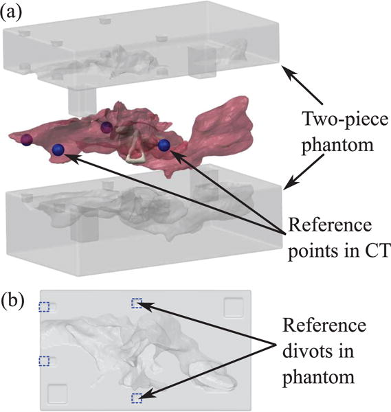
Fig. 8.

3D printed phantom used in the experiment. (a) Exploded view of two-piece phantom and mesh of ME used to generate the phantom geometry. Reference points (shown as blue spheres) were selected around ME in the CT scan to be used for registration with the phantom. (b) Planar view of bottom side of phantom. Divots corresponding to the reference points in the CT scan are outlined in blue dashed lines. These divots can be localized in the video of the experimental insertion to align the video with the CT scan.
