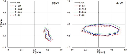
Figure 4.

IsoCal results for phantom offset positions showing the lateral (X) and longitudinal (Y) offsets in a full gantry rotation between the MV (left) and kV (right) imager centers and the projected treatment isocenter for four offset phantom positions. A: phantom aligned with room lasers; B: phantom offset about 5 mm laterally; C: phantom offset about 5 mm vertically; D: phantom offset about 5 mm longitudinally; E: phantom offset about 5 mm each of the three directions.
