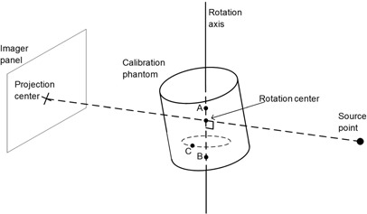
Figure A.1.

Geometry for the rotation center estimation. All parameters are calculated in the gantry coordinate system; thus, the phantom appears to be rotating. Two fixed points in the phantom, A and B (not necessarily BB locations), are identified as points with no transverse sinusoidal motion; these define the rotation axis. Point C is an example of a point that will be rejected as a possible rotation axis point because it moves in sinusoidal motion as the phantom rotates. Note that the rotation axis need not correspond with the symmetry axis of the cylinder. The rotation center and projection center can be calculated from the rotation axis and the location of the source point.
