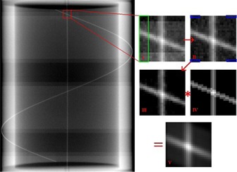
Figure 5.

An illustration of the wire intersection detection algorithm. The original image, which may contain banding artifacts, was cropped to a pixel region of interest (I). Banding artifacts were removed by looking for adjacent row average differences, located within the green rectangle of image I, larger than a given threshold value. A background noise reduction was applied to the ROI by subtracting the maximum pixel value of the blue boxes from image II. A 2D convolution of image III with a reference image (IV) was calculated to produce a final image (V). A centroid calculation was performed on a pixel square centered on the maximum intensity pixel in image V to determine the intersection coordinate.
