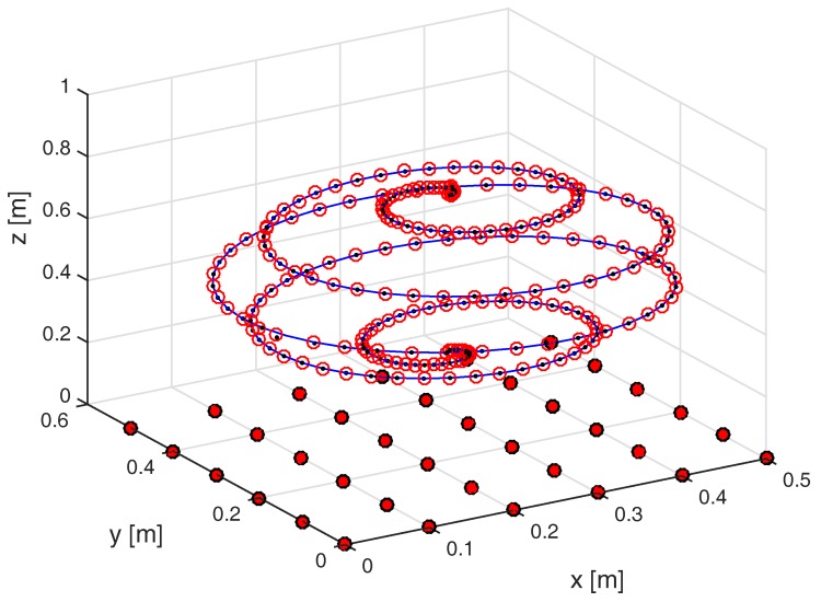
Figure 4.
Trajectory used for the numerical simulations. Sensing coils are placed on the plane and denoted by red-filled circlets. The true trajectory of the field-generating coil is marked as a solid blue line, the trajectory estimated by the mutual inductance method by black dots, and that estimated by the magnetic dipole method by red circlets.

