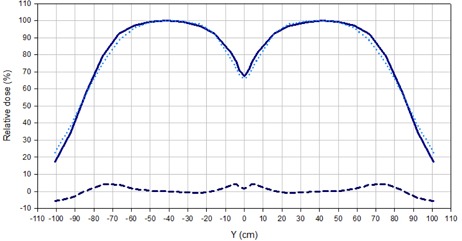
Figure 3.

Comparison of longitudinal profiles for the adjacent field technique, normalized to 100% at the center of each field. The solid line corresponds to a 6 MeV beam without filter and the dotted line to a 9 MeV beam with 8 mm acrylic degrader. The dashed line indicates the difference.
