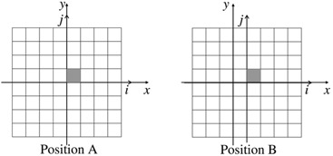
Figure 1.

Sketch of two steps of calibrations: irradiation A, the center of the EPID at the coordinates , and irradiation B, at , respectively. The gray pixel is the reference pixel and its coordinates (linked to the EPID (i,j) system) are in both A and B configurations .
