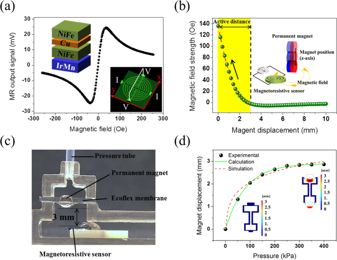
Figure 2.
MR sensing element characteristics for magnetic synapse. (a) Output signal profile of MR sensing element measured by four-probe method. The external magnetic field was applied along the x-axis perpendicular to the exchange bias field direction. The MR sensing element consists of Ta/NiFe/Cu/NiFe/IrMn/Ta thin films with a spin-valve structure. The magnetic field sensitivity was 2.79 mV/Oe in the range of +300 Oe. The inset shows an optical 3D image of the multi-ring MR sensing element. (b) Finite element simulation (ANSYS, Maxwell 16.1) showing the correlation between the vertical position of the permanent magnet and the magnetic field strength present at the MR sensing element. The simulation was carried out to determine the optimum initial position of the permanent magnet relative to the MR sensing element. The magnetic field strength decreases as the vertical distance of the permanent magnet changes from 0 mm to 3 mm, which is categorized as the active distance. (c) Cross-sectional image of magnetic synapse with air tube connected. The initial position of the permanent magnet was 3 mm from the MR sensor, as determined by finite element simulation. (d) Permanent magnet displacement calculated from the measured output signal of the MR sensing element versus applied tactile pressure. Finite element simulation was carried out by COMSOL Multiphysics 5.2, hyperelastic module.

