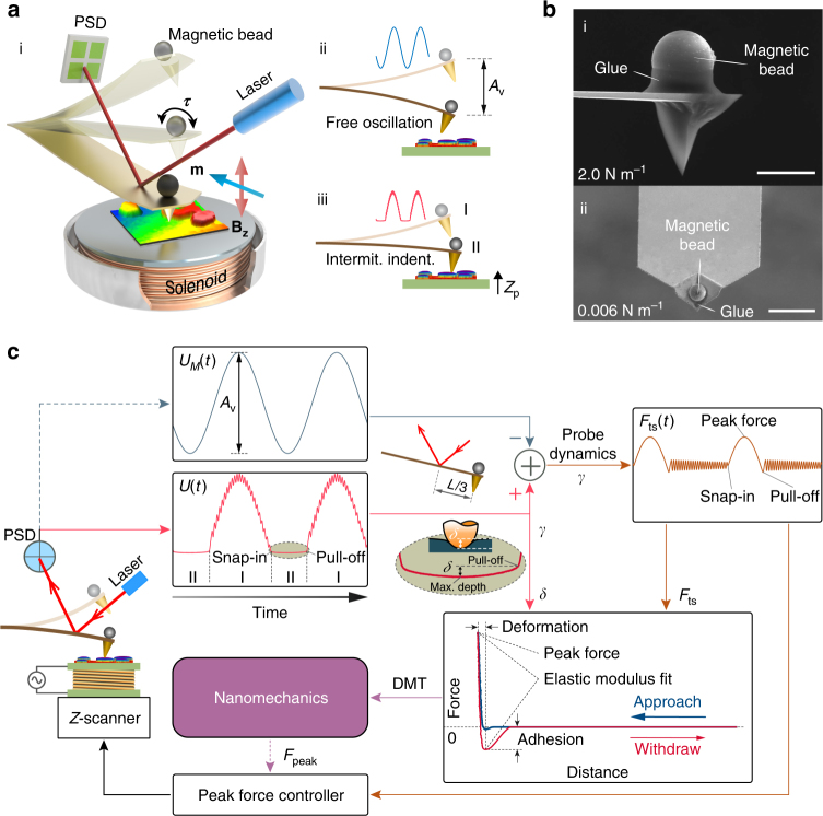
Fig. 1.
Scheme of magnetic drive peak force modulation AFM. a (i) Design of the experimental setup in which a magnetic bead probe is oscillated at an off-resonance frequency by a magnetic torque τ in an AC magnetic field (B z) generated by the solenoid underneath. (ii) The probe oscillates near the sample surface with a free amplitude of A v and (iii) intermittently indents the sample through the translation of the Z piezo-scanner. b SEM images of the probes with spring constants of 2 N m−1 (i) and 0.006 N m−1 (ii) attached with Ø11.4 μm and Ø3.8 μm magnetic beads, respectively. Scale bar, 10 μm. c Block diagram depicting the data processing flow and feedback control of the peak force. The tip-sample interactive response (F ts) (dark orange) and the indentation depth (δ) can be directly obtained from probe responses U(t) with (pink) and U M(t) without (dark blue) contact on the sample when the laser spot is located at two-thirds of the length (L) of the probe. The nanomechanical properties can then be quantified using the acquired force-distance data

