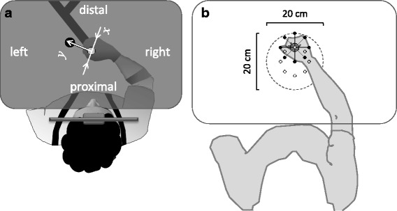
Fig. 1.

Schematic description of the experimental setting (top view). a The participant held the handle of a robotic manipulandum (indicated onscreen by a red disc; not shown), which allowed planar reaching movements from a start position (white onscreen disc (here gray) to a target position (blue onscreen disc; here black) and provided assisting and guiding forces as needed. Hand’s grip was maintained via a special glove and the forearm was supported against gravity (not shown). The participant leaned his/her head against a headrest, maintaining upright seating posture (ensured using a harness). The horizontal display occluded the hand and the manipulandum from vision. The start-to-target axis (y) and its perpendicular axis (x) correspond to the axes of the assisting and guiding forces, respectively, which were provided during the arm movement as needed by the robot. Adapted from Howard et al. (2009). b The reaching workspace used for mapping performance. The locations of the 8 targets, used in the mapping sessions, are indicated by small open circles. An example of the arm posture when the hand located at the 90o target is shown. Participants were tested with 5cm reaches to each target from 8 start locations (indicated, for the example target, by small black dots). The dashed circle indicates the extent of the mapped workspace. The drawing reflects the actual relationship of target and start locations and arm posture, based on a photograph taken with a healthy participant
