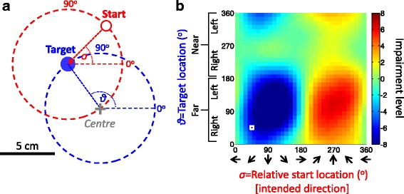
Fig. 2.

Mapping impairment across the workspace. a The reaching movement workspace for mapping motor performance is defined by a range of targets and their corresponding relative start locations. All targets are located on a blue circle around a pre-defined central location on the display (illustrated by a gray cross, neither circle or cross was visible to participants). The possible start locations also lie on an unseen circle around each target (illustrated for one target by a red dashed circle; see also Figure 1b). The location of the target and relative start location are defined in angular coordinates. An example of a pair of target location ϑ =135o (blue disk) and relative start location σ=45o (red circle) is shown. Note that each relative start location corresponds to an intended movement direction, and that each pair of target and start location coordinates is a point on a 2D map. b An illustration of an impairment map. The impairment level (here in normalized units) in each movement task was mapped in terms of its target and relative start condition. The coordinates of the example movement in panel a are shown on the map by a white square. Note that the map coordinates are radial and NOT spatial coordinates (x,y)
