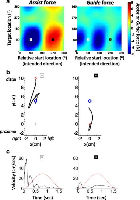
Fig. 3.

Impairment maps. a An example of Assist and Guide force maps shown for one UL hemiparetic stroke participant (participant 1; allotted movement time=1.6 sec, guiding stiffness=2.7 N•cm-1). Negative (blue) and positive (red) values denote forces that are provided to oppose and assist movement direction, respectively. The white and black squares refer to the conditions shown on the left and right of panel b, respectively. b Examples of reach trajectories for two individual movements performed by Participant 1. The left panels correspond to the map coordinates in panel a labelled by a white square. The right panels correspond to the maps’ coordinates labelled by the black square. The red and blue circles denote start and target location, respectively. The grey cross indicates the centre of the workspace. Note that the two conditions differ in start location but share same target location. c example of speed time series for the same example movements shown in in panel b The black line indicates actual reaching speed and red line indicates ideal minimum jerk speed profile computed according to the allotted movement duration and displacement [36]. Note the very fast rebound-like movement in the left graphs of panels b and c. The later correction of the movement (upwards towards the target; panel b) is a result of the opposing Assist force provided by the robot. Note also the very slow movement in the right graphs (panels b and c) and the failure to reach the target even with robot assistance, due to high elbow flexor tonus and, potentially, weak elbow extensors
