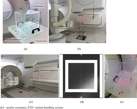
Figure 7. QA phantom and phantom attachment (a) (blue (V1–V5) and red points (H1–H5) are small beads on the vertical and horizontal planes); (b) QA phantom on the QA stand and (c) on the treatment table (annotations Xf, Yf and Zf show room coordinate axis defined by IEC (14) ); (d) QA phantom X‐ray image in the vertical direction (blue points (V1–V5) are small beads positioned on the QA phantom vertical planes); (e) CT gantry laser QA.

