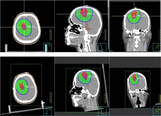
Figure 3.

Example of image and structure rotation for case #8 with rotation in three axes. The upper row shows the original images and target structures in the three orthogonal planes; the lower row shows the rotated images and target structures depicting rotational setup errors.
