
Figure 2.
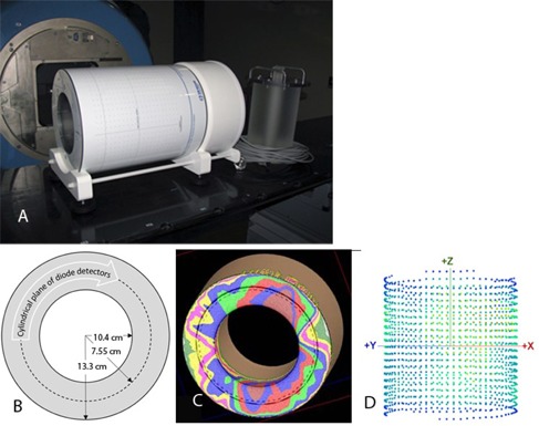
The 3D dosimetry device: (a) overview with an optional PMMA plug on the right; (b) axial cross section of phantom and detector geometry; (c) rotational plan calculated on the virtual model of the device; and (d) 3D view of the diode detector positions, as seen from a 45° gantry angle.