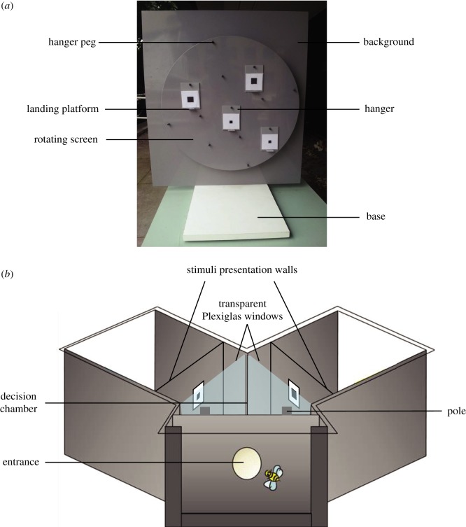
Figure 3.
(a) An image of the rotating screen used for Experiment 1 with labels to show basic parts of the apparatus. (b) A diagram of the Y-maze used in Experiment 2 with labels showing the basic parts of the apparatus. A bee enters through the small hole into the decision chamber where it is presented with two stimuli behind Plexiglas windows and must make a decision on which pole to land on for a reward. (Online version in colour.)

