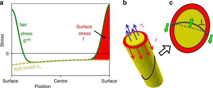
Fig. 1.
Stress in a nanowire and its impact on dislocation glide. Schematic representations. a Green line, stress profile along a linear section through the wire. The actual stress S net may be decomposed into bulk stress σ C (yellow dotted line) and surface stress f (red shaded area). b Balance of force on a normal cross-section. Surface regions (red) experience tensile stress, which is represented by the surface stress and which is compensated by an oppositely-signed surface-induced stress σ C in the bulk (blue). c Dislocation (gray line) on an inclined cross-section. Shear components of stresses from a give rise to Peach–Köhler forces that mutually compensate

