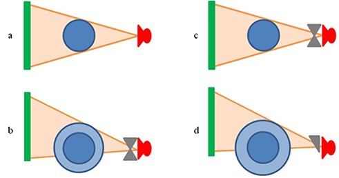
Figure 1.

Scanning configuration for each imaging protocol used. As seen, the collimation was changed and the detector panel was shifted orthogonal to the kV beam axis when a larger FOV was required. XVI head scan, no bow‐tie filter, imaging panel centered, 27 cm FOV; (b): XVI chest and pelvis scan, bow‐tie filter, imaging panel shifted, 41 cm FOV; (c): OBI head scan, bow‐tie filter, imaging panel centered, 25 cm FOV; (d): OBI chest and pelvis scan, half bow‐tie filter, imaging panel shifted, 45 cm FOV.
